MSS SP-75

Spread the love

MSS SP-75 SPECIFICATION FOR HIGH-TEST, WROUGHT, BUTT-WELDING FITTINGS

MSS SP-75  covers factory-made, seamless and electric fusion-welded carbon and low-alloy steel, butt-welding fittings for use in high pressure gas and oil transmission and distribution systems, including pipelines, compressor stations, metering and regulating stations, and mains.

MSS SP-75 governs dimensions, tolerances, ratings, testing, materials, chemical and tensile properties, heat treatment, notch toughness properties, manufacture and marking for high-test, butt-welding fittings NF’S 60 and smaller. Dimensional requirements for NPS 14 and smaller are provided by reference to ASME B16.9.

Welding Positions

Spread the love

For Groove Welds

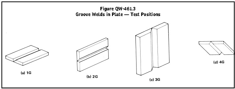
PLATE positions

1G Flat Position. Plate in a horizontal plane with the weld metal deposited from above.

2G Horizontal Position. Plate in a vertical plane with the axis of the weld horizontal.

3G Vertical Position. Plate in a vertical plane with the axis of the weld vertical.

4G Overhead Position. Plate in a horizontal plane with the weld metal deposited from underneath.

QW 461.3


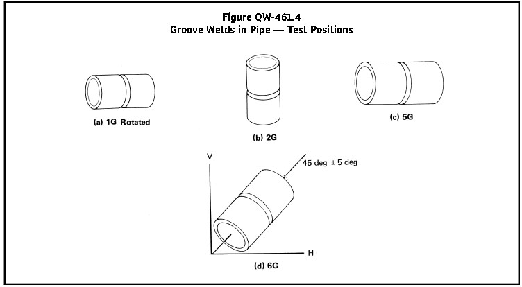
PIPE positions

1G Flat Position. Pipe with its axis horizontal and rolled during welding so that the weld metal is deposited from above.

2G Horizontal Position. Pipe with its axis vertical and the axis of the weld in a horizontal plane. Pipe shall not be rotated during welding.

5G Multiple Position. Pipe with its axis horizontal and with the welding groove in a vertical plane. Welding shall be done without rotating the pipe.

6G Multiple Position. Pipe with its axis inclined at 45 deg to horizontal. Welding shall be done with out rotating the pipe.

QW461.4

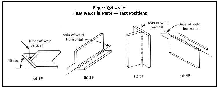
 For Fillet Welds

1F Flat Position. Plates so placed that the weld is deposited with its axis horizontal and its throat vertical.

2F Horizontal Position. Plates so placed that the weld is deposited with its axis horizontal on the upper side of the horizontal surface and against the vertical surface.

3F Vertical Position. Plates so placed that the weld is deposited with its axis vertical.

4F Overhead Position. Plates so placed that the weld is deposited with its axis horizontal on the underside of the horizontal surface and against the vertical surface.

QW465.1

Fillet weld and groove weld

Spread the love

Fillet weld is a weld of approximately triangular cross section joint two surfaces approximately at right angles to each other in a lap joint, tee joint, or corner joint.

Groove weld is a weld made in groove formed within a single member or in the groove between two members to be jointed. The standard types of groove weld are as follows:

(a) square groove weld

(b) single – Vee groove weld

(c) single – bevel groove weld

(d) sing –  U groove weld

(e) single – J groove weld

(f) single – flare – bevel groove weld

(g) single – flare – Vee groove weld

(h) double – Vee groove weld

(i) double  – bevel groove weld

(j)  double  – U groove weld

(k)  double  – J groove weld

(l)  double  – flare – bevel  groove weld

(m) double  – flare – Vee  groove weld

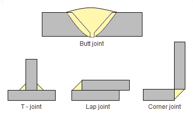
Basic Welding Joints – Butt welded and Fillet welded joints –

four basic weld joints

basic weld joints


A‐Numbers (ASME BPVC IX – 2013)

Spread the love

Classification of Ferrous Weld Metal Analysis for Procedure Qualification

A‐Numbers

Table QW-442

A‐No. Types of Weld Deposit Analysis, % [Note (1)] and [Note (2)]
C Cr  Mo Ni Mn Si
1 Mild Steel 0.20 0.20 0.30 0.50 1.60 1.00
2 Carbon‐Molybdenum 0.15 0.50 0.40–0.65 0.50 1.60 1.00
3 Chrome (0.4% to 2%)‐Molybdenum 0.15 0.40–2.00 0.40–0.65 0.50 1.60 1.00
4 Chrome (2% to 4%)‐Molybdenum 0.15 2.00–4.00 0.40–1.50 0.50 1.60 2.00
5 Chrome (4% to 10.5%)‐Molybdenum 0.15 4.00–10.50 0.40–1.50 0.80 1.20 2.00
6 Chrome‐Martensitic 0.15 11.00–15.00 0.70 0.80 2.00 1.00
7 Chrome‐Ferritic 0.15 11.00–30.00 1.00 0.80 1.00 3.00
8 Chromium‐Nickel 0.15 14.50–30.00 4.00 7.50–15.00 2.50 1.00
9 Chromium‐Nickel 0.30 19.00–30.00 6.00 15.00–37.00 2.50 1.00
10 Nickel to 4% 0.15 0.50 0.55 0.80–4.00 1.70 1.00
11 Manganese‐Molybdenum 0.17 0.50 0.25–0.75 0.85 1.25–2.25 1.00
12 Nickel–Chrome—Molybdenum 0.15 1.50 0.25–0.80 1.25–2.80 0.75–2.25 1.00

NOTES:
(1) Single values shown above are maximum.
(2) Only listed elements are used to determine A-numbers.

GATE VALVE BB CS

Spread the love

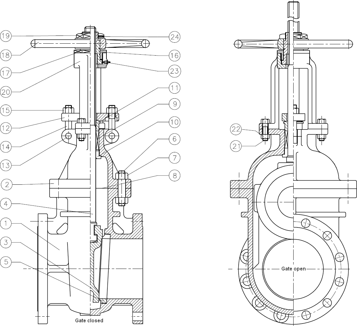
Yoke sleeve

The upper portion of the Yoke Sleeve is hexagonally tapered to fix the handwheel. The standard material of the Yoke Sleeve is Nodular Ni-resist D2 with over 1150℃(2100°F) dissolution point in accordance with API Std. Specifications.

Bolting

The body-bonnet bolts are manufactured in accordance with API Std. 600 specifications. The nuts also strictly conform with ANSI B 1.1. The stud-blot nuts, hexagonal, rigid and hot-forged, bear material notation as well as do the bolt nuts made according to ANSI B 18.2.2.

Bonnet

The bonnet and valve body have the same wall thickness. The body-bonnet flange drilling is spot-faced to exactly meet stud-bolt nuts. The bonnet back seat bushing guarantees packing replacement even with when the valve is fully opened. The stem packing dimensions of the stuffing box are in accordance with API specifications.

Stem

The machined forged stem comes with a T-shape head, which connects the slot of the wedge. The spherically shaped contacting surface of the head gives greater strength and durability. The stem dimensions are in accordance with API Std. 600 specifications.The heat treated stem delivers adequate mechanical properties as well as excellent hard surface . Furthermore. Opening/shutting friction Is minimized by accurate machining and tapping.

Seat

Bottom seated type sealing rings are welded or screwed into the body. The sealing surface is finished by lapping. They are forgings that have been heat treated deliver the best mechanical properties and required hardness.The differences of hardness between seats and wedge is in accordance with API specifications.

Flexible wedge

The standard disc of our valves is a one-piece flexible wedge. Slots are machined on both sides of the wedge which allow it to travel correctly in the integrally cast body guides.
The wedge sealing surfaces have been accurately machined, grind and lapped to a mirror finish to prevent leakage and eliminate galling.

Body

The Cast steel body is designed to insure a wall thickness which is greater at any point than the minimum specified by API Std. 600. Special care has been taken with the design of the Class 150 valve body so that the elliptically shaped center section is free from intensified stresses in the critical area. The body of above Class 300 are made circular in shape as much as possible to minimize distortion even under extreme operating conditions. Inlet and outlet port dimensions conform with ANSI B 16.5 Pipe Fitting The welded in type seat ring is standard to insure interchangeability. Except for Class 150 the standard body-bonnet joint is male and female.

Design

The cast steel gate valves are designed and manufactured to provide maximum service life and dependability. All gate valves are full ported and meet the requirements of  API 600 & 6D, BS1414 & BS EN 1984 and generally confirm to ASME B16.34. Valves are available in a complete range of body / bonnet and trims.

Introduction of Directly Buried Three Layer PE Anti-corrosive steel Pipe

Spread the love

The current domestic anti-corrosive steel pipe adopt epoxy coal tar anti-corrosion, welding epoxy powder(FBE, glassfiber anti-corrosive) and three-layer PE, anticorrosive, but from  the anti-corrosion structure should be the first choice.
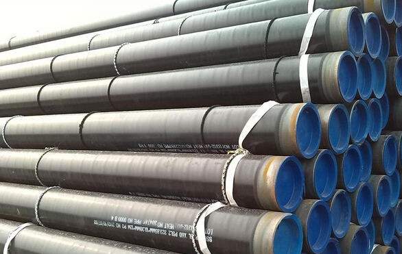
3 PE pipe

Structure of three layer PE anti-corrosive pipe

Three layer PE anti-corrosive steel pipe carry out the national standard GB/T23257 – 2009. Anti-corrosion steel pipe with inner layer of epoxy powder coating, middle layer of adhesive, outer layer of polyethylene.

Technological process of three layer PE anti-corrosive pipe

1. Shot blasting degusting processing for the steel pipe

Before shot blasting degusting, with medium frequency induction heater, the steel pipe should be preheated to 40-60 degree, and then through the shot blasting machine to remove the water, oil and dirt contamination, derusting grade is up to GB/T8923-1988 standard, Sa2.5 level (nearly white level) requirements, the depth on the surface of the steel anchor pattern from 40 to 100 microns.

2. Epoxy powder coating

Before spraying, the steel pipe will be wrapped in kraft paper on both ends, then use medium frequency induction heater, heated the steel pipe to 190-230 degree, the electrostatic spraying method is adopted to epoxy powder as required amount of powder coating to the steel pipe surface, in the high temperature, combination with base material fastness, its anticorrosion performance is superior, the good resistance to chemical corrosion, coating surface density is smooth, wearable, and anti-high temperature.

3. Extruded adhesive

According to requirement of the thickness of adhesive layer and polyethylene, by adjusting the extrusion machine lord motor and screw revolution, to meet the requirements of extrusion amount. When the epoxy powder in a gel form, we adopt lateral winding technology, make the adhesive and PE coated on steel pipe, adhesive epoxy powder, polyethylene polymerization to form a three layer structure, after molding, with three rows of roller, make three layer structure fusion compaction, make it a whole system with smooth surface, without bubble and defect.

Adhesive performance is stable, strong adhesive force, uniform film-forming.

Temperature of PE extrusion is 230-260 degree, PE aging corrosion resistance is strong, good environmental stress cracking resistance and elongation properties.

4. Cooling of coating pipe 

According to the requirements of the three layer structure of the material properties, it requires slow cooling, temperature of cooling pipe should not exceed 60 degree.

5. Jeeping

In the production process, using online electric spark leak detector for coating 100% of leak detection voltage is 25 KV. It requires no funneled under 25 Voltage leak detection.

6. Coating products processing

Use groove grinding machine for pipe end for processing and tags.

Main materials

Epoxy powder adhesives and polyethylene epoxy powder material, for example, FBE form American 3M company, Dupont resin adhesive and domestic high quality polyethylene materials.
Installation Method of Pre-insulated Pipe

Spread the love

According to whether the temperature of the overall pipeline welding is equal to the temperature of backing, the installation method can be divided into:

Cold Installation

The temperature of the overall pipeline welding is equal to the temperature of backing.

The installation processes of the pipeline welding and groove backfill are finished in the cold condition. In the cold ambient temperature, the pipeline is in zero stress state. In running condition, the stress and internal force of anchorage section and the displacement of compensation device in the sliding section are a bit large because the rising temperature is large.

It can backfill timely during the pipeline construction. It can save large quantity of money because it maximum reduce of even no need to install compensator and fixed support. But the pipeline stress and internal force increase, sometimes it’s necessary to strengthen the tee or increase the embedding depth.

Prestress Installation

The temperature of the overall pipeline welding is higher than the temperature of backfilling.

Prerelease the thermal expansion deformation from ambient temperature to preheating temperature. when the pipeline temperature returns to the ambient temperature, the pipeline is in the tensile stress station to make a prestressing effect. In running condition, because of prerelease of some thermal expansion deformation and the stress and internal force of anchorage section, the displacement of compensation device in the sliding section have a large degree of decline.

According o the sequencing of the pipeline welding and trench backfill, the prestress installation can be divided into preheat installation method and one-time compensator installation method.

Preheat Installation Method

Preheat the pipeline before backfilling, when the pipeline is heated to he preheat temperature, then weld th pipeline and backfill. In the preheat installation method, the release of thermal deformation is under the condition of the groove exposure. It can make immediate uniform distribution of prestressing effect in the pipe section.

One-time Compensator Installation Method

Preheat the pipeline after backfilling, installing one-time compensator in the pipeline to absorb thermal deformation from ambient temperature to expected preheating temperature. After teh pipeline welding, other grooves can be backfilling except the pipeline near the one-time compensator. In the process of first time heating, when the one-time compensator compensation dimension is reaching the thermal deformation prereleased at the compensation section, this one-time compensator can be welded to realize the whole pipeline welding.

In the one-time compensator, installation method, the thermal deformation prerelesed is under the condition of groove backfilled. The release of thermal deformation will be limited by the soil friction. The actual preheat temperature of welding one-time compensator is higher than expected preheat temperature, and only through times of temperature changing can make an effect of uniform distribution of prestressing effect for the whole pipeline.

All in all, compared with cold installation, the fixed pier thrust and compensator compensation dimension fo prestress installation will decline, but the stability of whole and partial pipeline will improve.


Pre-Insulated Pipe Joint on the Construction Site

Spread the love

Heat shrinkable belt type sleeve joint

Heat shrinkable belt type sleeve joint is made by special import heat shrinkable belt, through the flame heating contraction, make the tight connection of the HDPE outer protection pipe and the joint sleeve, not only ensure the sealing of joint and water proofing property, and can absorb the axial displacement of the pipe, it requires simple equipment and instrument and it really convenient and practical for small diameter pipeline.

Electric welding type socket connectors

Sleeve joint with electric welding is through special plastic welding equipment to heat the wire in the polyethylene casing, by heating and a certain pressure, make joint casing and polyethylene outer pipe as a whole system.

Welding tensile strength of the joint is not lower than the shell material, it is stable and reliable, easy to operate, and can do 100% air test.

Adopting professional electrical control box to make automatic control of heating process, through the control of the different process parameters, optimal melting effect, so as to ensure the quality of welding joint and sealing, and deliver higher axial force.