A SAMPLE OF WELDING SPECIFICATION

Spread the love

1.1 SCOPE

This specification defines the minimum requirements for the welding and inspection of welded fabrications and steel structures when supplied as part of mechanical equipment.

Welding procedure qualifications and welder performance qualifications shall be carried out in accordance with:

• ASME IX and

• AWS D1.1

AWS D1.1. Prequalified permitted only on fillet welds or partial penetration welds, full penetration butt welds shall be supported by a PQR.

Note: ISO/EN codes may be accepted at the discretion of the Engineer.

Welding procedure specifications and procedure qualification records shall be submitted to the Engineer for approval prior to the start of welding.

Weld processes acceptable to the Engineer, provided they are qualified, include:

• Gas Metal Arc welding (GMAW)

• Shielded Metal Arc welding (SMAW)

• Gas Tungsten Arc welding (GTAW)

• Submerged Arc welding (SAW)

• Flux Cored Arc welding (FCAW)

• Surface Tension Transfer welding (STT)

Any other process is subject to the approval of the Engineer.

Preheat temperatures shall be established in procedure qualifications or when specified in the applicable code of practice.

When preheat is mandatory for welding, the preheat temperature shall also apply for tack welding.

Post weld heat treatment, (PWHT) where required, shall be carried out in accordance with the relevant procedure and specification.

All PWHT procedures shall be submitted to the Engineer for approval before work is started. Testing shall be done on the heat-treated item to confirm its compliance and not on a similar piece of material treated at the same time. This shall be done by allowing for an extension of the component, of the same dimensions, which is cut off for testing after heat treatment. These will be regarded as coupon plates.

Stress relieving shall be performed as required on the drawings which shall state the required

temperature and time at that temperature, the maximum or minimum heating and cooling rate in EC per hour.

Records shall be kept of the temperature and heating cycle. A current calibration certificate of the furnace instrumentation shall be produced on request prior to the material commencing heat treatment.

Only welding consumables complying with a recognised classification system shall be used for production welding.

Consumables shall be stored in clean dry conditions to prevent moisture pick up and mechanical damage, electrode types shall be separated and identified for type and size.

Where required, electrodes shall be baked in accordance with manufacturers’ recommendations.

All electrodes that undergo baking should be issued in accordance with a procedure that will record all baking details. “Hot boxes” shall be used for manual metal arc electrodes low hydrogen types E 7018, E 7015, E 7016, and E 7024.

Surfaces to be welded shall be smooth, uniform, and free from tears, cracks, or other defects that would adversely affect the welding quality or strength of weld surfaces. Surfaces adjacent to a weld shall also be free of loose or thick scale, slag, rust, moisture, grease, paint, or other foreign material that will prove detrimental to weld quality.

Tack welds shall be subject to the same quality requirements as the final welds except when tacks are not to remain as part of the weld.

Tack weld’s, which are incorporated into the final weld, shall be made with electrodes meeting the requirements of the final welds and shall be thoroughly cleaned. Multi-pass tack welds shall have cascaded ends. Tack welding shall only be performed by fully qualified welders on all equipment other than structural steel and platework.

In assembling and joining parts of a structure, or build up of members, and in welding reinforcing parts to members, the procedure and sequence shall be such as will minimise distortion and shrinkage.

Insofar as is practicable, all welds shall be deposited in a sequence that will balance the applied welding heat whilst welding is in progress.

The direction of the general progression in welding on a member shall be from points where the parts are relatively fixed in position with respect to each other towards points where they have greater freedom of movement.

Joints expected to have significant shrinkage should usually be welded prior to the joints where less shrinkage is expected and with as little restraint as possible.

In making welds under conditions of severe external shrinkage restraint, the welding shall be carried out continuously to completion or to a point that will ensure freedom from cracking before the joint is allowed to cool to below the minimum specified preheat temperature.

All welds shall be examined for acceptable weld profile and finish. The weld shall have uniform contour and be free from large ripples.

Fillet weld leg lengths shall not be less than the values required by detail drawings and shall not differ from each other by more than 1.5 mm. Joints at all external stop-starts shall merge smoothly and shall not show a pronounced hump or crater in the weld surface.

Intermediate undercutting is permitted provided that the depth does not exceed 10% of parent metal thickness or 0.8 mm whichever is the smaller.

Incomplete filling of butt joints is prohibited. Butt welds shall have uniform convexity to a maximum height of 3 mm or t/5 whichever is smaller, where “t” is the thickness of parent material. In butt welds there shall be full fusion, along the length of the weld unless the relevant specification allows a certain length.

Provided there is complete root fusion, root concavity is acceptable if the thickness of the weld is not less than the parent metal.

The weld surface shall be free from cracks, porosity, shrinkage, cavities, and slag. The weld surface and adjacent parent metal shall be free of arc strikes, chipping marks or weld spatter.

NDT, where required, shall be carried out in accordance with a recognised code of practice with procedures and qualified personnel.

Acceptance standards shall be in accordance with the relevant specification.

All NDT procedures and operator’s qualifications shall be submitted to the Engineer for approval. Operator qualifications shall, as a minimum, be to acceptable international qualifications.

Machining shall be accordance with the drawings. Any deviation there from shall be approved by the Engineer in writing.

This shall be done in accordance with the following DRA project specifications:

• SPXXXXXXXX – Corrosion Protection and

• SPXXXXXXXX – Colour Coding and labelling of Plant.

Inspection and Testing shall be done in accordance with the requirements of the order and the Quality Plan where applicable.

Where the following procedures are specified, they shall be done in accordance with the standards as listed below:

12.1 RADIOGRAPHIC EXAMINATION

ASME V 2007, AWS D1.1 2006.

12.2 ULTRASONIC EXAMINATION 

ASME V 2007, AWS D1.1 2006.

12.3 MAGNETIC PARTICLE EXAMINATION

ASME V 2007, AWS D1.1 2006.

12.4 DYE PENETRANT TESTING

ASME V 2007, AWS D1.1 2006.

Other internationally recognised standards may be used at the discretion of the Engineer.

12.5 FINAL ACCEPTANCE

All the acceptance parameters shall be demonstrated by the Vendor and witnessed by the Engineer. When all the requirements have been met the Vendor shall provide written records of the testing to the Engineer who shall then accept the equipment as complete.
POSITIVE MATERIAL IDENTIFICATION-PMI

Spread the love

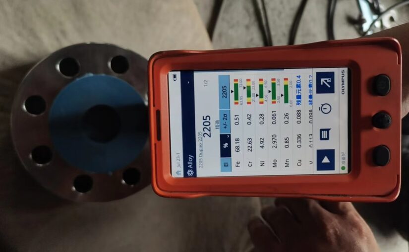
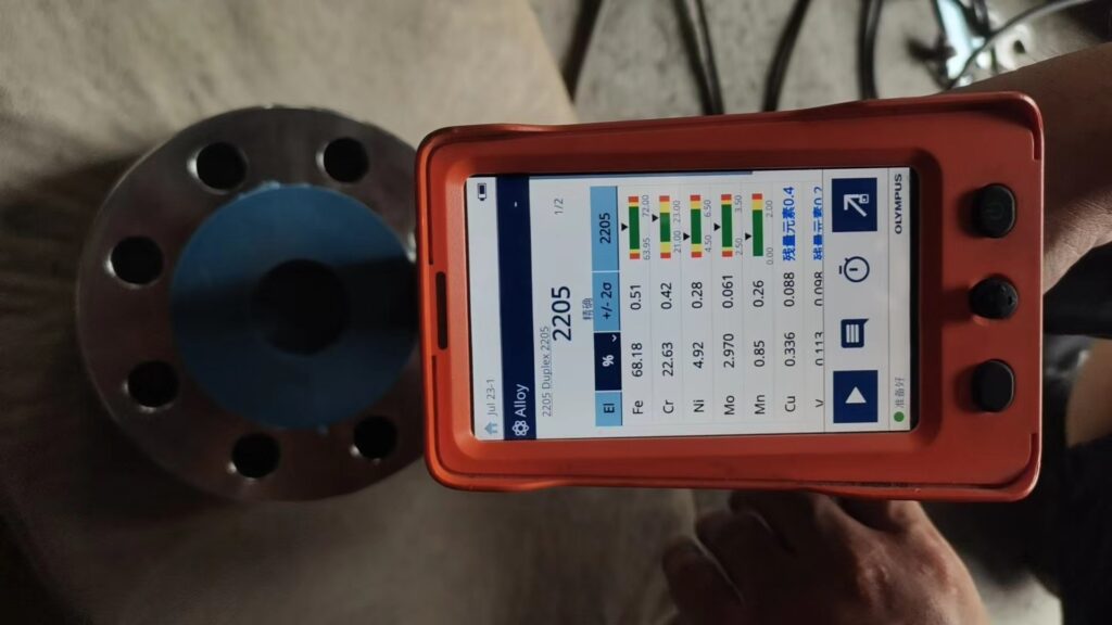
The purpose of PMI is to ensure that materials are correctly supplied and/or installed, as specified. This guideline is applicable to pressure-retaining equipment and piping fabricated from Cr-Mo, Cr-Ni-Mo, Ni alloy steel, Ni based alloys, and other alloys as specified in the Purchase Order and/or related documents.
Materials requiring PMI per this guideline are identified in Table 1. Components exempt from PMI are listed following Table 2. When required by the Purchase Order, PMI testing shall be performed on each alloy component of a pressure-retaining assembly. This shall include each individual segment of pipe, welds, each plate, and other base materials (i.e., forgings, fittings,
furnace tubing, tube sheets, etc.) provided by the Seller. Alloy portion of clad and/or weld overlay components shall receive PMI testing, regardless of whether the cladding or overlay has been considered in the pressure calculations. Carbon steel components are exempt from PMI unless alloying elements are critical to corrosion resistance, therefore a requirement for PMI of CS will be noted in the Purchase Order. As an example, a minimum of 0.10% silicon content is critical to the corrosion resistance of carbon steels in sulfidizing environments.

Table 1: Materials and Components Requiring PMI

ITEMVERIFICATION REQUIRED
Carbon Steels1 or Cast IronsNo – Unless noted in P.O.
Alloy Pressure Piping (Spools, Fittings, Straight-Run Pipe)Yes – 100%
Alloy Pressure Vessels Components (Pressure retaining)Yes – 100%
Alloy ValvesYes – 100% Body, Bonnet, stem only, as designated by P.O.
Alloy PumpsYes – 100% Casing/Impeller only
Alloy Tubing (1/2” diameter and smaller)No
Alloy Instrumentation, Pressure ChambersYes – 100%
Alloy Bolting – A193 B7/ B16, A320 L7Yes – 1% of total studs/bolts, 1 check per heat (min.)
SS Bolting – A193/A320 B8/B8MYes – 1% of total studs/bolts, 1 check per heat (min.)
Alloy Heat Exchanger TubingYes – 2.5% of total tubes, minimum one check per heat
Carbon steel welds (pressure retaining)No – Unless noted in P.O.
Alloy Pressure Retaining Welds in Contact with Process FluidsYes – 100% of completed welds (cap or root)
304/304L Stainless steel weldsNo – Unless noted in P.O.
Other SS pressure retaining weldsYes – 100% in accordance with this specification
Alloy Weld OverlayYes – 100% in accordance with this specification & component specific fabrication specification.
Alloy RTJ (Ring) GasketsYes – 100% (1 test per each heat)
Alloy CladdingYes – Once per piping component or fitting, and each shell course component (e.g., HEX channel) for equipment.

The following items are exempt from PMI, unless specifically designated for PMI by the Purchase Order:
a) Alloy components where the alloy is installed for product purity considerations, including lube oil, and seal oil piping and tubing.
b) 300 series stainless steel selected for Cryogenic application or specifically for resistance to Wet Co2.
c) Internal machinery parts.
d) Internal instruments parts (including pressure parts of gages)
e) Internal non-pressure retaining baffles, trays, tray clips, supports, pall-rings, support rings, etc.
f) Electrical components.
g) Non-pressure containing welds.
h) Internal valve components.
i) Alloy components that have been substituted as a “higher” alloy for Carbon Steel or substitutions such as 316 for 304 or B8M for B8.
j) Gaskets (except RTJ gaskets).
k) Copper alloys; Titanium and it’s alloys; Brass and Bronze alloys.
l) Off-the-shelf (e.g., “buy what they make” components)

Table 2: Critical Elements Required for PMI

Alloy Categories & Specific AlloysElements to be Verified
300 Series Stainless
(304, 316L, 310, 321, 347, etc.)
Cr, Ni, Mo
(plus: Cb or Ti for “stabilized” grades (321 & 347);
Carbon may also be required if specifically noted in the P.O.; For 304 Cr, Ni shall be verified)
6-Mo
(AL6XN, 254SMo, 904L, etc.)
Cr, Ni, Mo, Cu
Ni-Based
(Alloy C-22, Alloy 625, Monel, etc.)
Ni, Cr, Mo, W, Cu
Low-Alloy, General
(1¼ Cr-½ Mo, 2¼ Cr-1Mo, 5 Cr-1½ Mo, etc.)
Cr, Mo
Low-Alloy, 9 Chrome and Grade 91
(9 Cr-1 Mo and 9 Cr-1 Mo-V Modified)
Cr, Mo, V
400 Series Stainless
(405, 410, 410S, etc.)
Cr
(plus: C & Ni, for “S” grades, if specifically noted in the P.O.)
CA6NMCr, Ni, Mo
Duplex Stainless
(2205, 3RE60, CD-4MCu, Uranus 50, etc.)
Cr, Ni, Mo, Cu
Low-Ni Steel
(3½ Ni, 9 Ni, etc.)
Ni

General Requirements of a Tee – 950NB x 600NB 70MM Thickness- ASTM 860 WPHY65 + NACE MR0175 / ISO 15156-2

Spread the love

Tee – 950NB x 600NB 70MM Thickness- ASTM 860 WPHY65 + NACE MR0175 / ISO 15156-2
Qty – 1 off
Material Certification – EN 10204 3.2 type

General Requirements
1 All material shall be supplied with material test certificates (MTC) as per EN10204, type 3.2.
2 For stock items, MTC shall be supplied for review and approval prior to fabrication.
3 For Tee details refer drawing
4 Material to comply to ASTM A860 WPHY65
5 Material to comply NACE MR0175 / ISO 15156-2
6 Max hardness <= 22 HRC
7 Impact test as per A860
8 Material shall be killed, fine grain and heat treated according to NACE MR 0175 / material standard.
9 Max carbon content <= 0.20%
10 Max carbon equivalent <= 0.43%
11 Nb <=0.05%
12 Boron <=0.0005%
13 (Nb+V+Ti) <= 0.08%
14 S<= 0.005%
15 100% UT and 100% MPI to ASME Vlll Div 2 Sec 3.3.4.
16 Material certification to EN10204 Type 3.2 must include below :
Order No.
Grade of material
Cast no. and heat treatment no.
Melting and refining process.
Certified chemical analysis along with calculated carbon equivalent.
Certified record of mechanical properties including impact test.
Certified record of hardness.
Certified record of Heat treatment.
Certificate of Ultrasonic Test.
Certificate of MPI Test.
Material certification must include a statement that material meets the requirements of NACE MR0175 / ISO 15156-2.
Raw material certificates require for review.
17 Material must be HIC tested as per NACE MR0175 / ISO 15156-2
18 100% RT required on welded joints.
19 After bevel prap for the ends, UT/ MPI shall be performed

SPECIFICATION FOR INDUCTION BEND

Spread the love

1.This specification covers the design, materials, manufacture and supply of pipeline induction bends (hot bends).

2.CODE AND STANDARD
The pipeline induction bends shall conform in design, materials, manufacture, supply and performance, except where otherwise specified, with the current issued amendments of the following prevailing on the effective date of the Contract:
ASME B31.8 Gas Transmission and Distribution Piping Systems
ASME B31.4 Pipeline Transportation Systems for Liquid Hydrocarbons and Other Liquids
ASME B16.49 Factory-Made, Wrought Steel, Buttwelding Induction Bends for Transportation and Distribution Systems
API 5L Specification for Line Pipe
ASTM Standard Test Methods and Definitions for Mechanical Testing of Steel Products
API 1104 Welding of Pipelines and Related Facilities
ISO 15590-1 Petroleum and Natural Gas Industries – Induction Bends, Fittings and Flanges for Pipeline Transportation Systems – Part 1: Induction Bends
ISO 6761 Steel tubes – Preparation of Ends of Tubes and Fittings for Welding.
Where conflicts exist between this specification and other Drawing, standards, codes or specification, the most stringent shall be applied.

3.QUALITY SYSTEM
The Subcontractor shall maintain effective quality assurance, and quality control programs in accordance with BS 5750, Part 2, covering all aspects of the work. Quality Control ensures that quality requirements are determined prior to commencement of manufacture and, subsequently satisfies the requirements of the Contract throughout all phases of production and delivery.
The Contractor shall submit for the Company`s approval Quality Plan covering all aspects of manufacture, inspection and testing of the bends.

4.MATERIALS
The line pipe shall be supplied by the Contractor and manufactured in accordance with the Project Specification entitled “Material Specification for Pipelines”
The Contractor shall furnish hot induction formed bends from the above material in accordance with the requirements of this specification.
Generally, the bend shall be made from the mother pipe which same with pipes of piping class.
Contractor shall provide test rings to be used for weld procedure qualification test on site.
Test rings shall be 500mm long and shall be simulated to actual condition of the bend tangent part. The number and size of test rings required will be defined on the Purchase Order.

5.MANUFACTURING PROCEDURE QUALIFICATION
5.1.The Contractor shall produce a procedure for the manufacture of the bends for approval by the Company prior to its usage in production.
5.2.The Contractor shall qualify the manufacturing procedure by producing a procedure qualification test bend for each pipe grade, size and thickness. The dimensions of each test bend shall be the same as the dimensions of the corresponding production bends.
5.3.The manufacturing procedure and heat treatment shall be the same in all aspects as those corresponding production bends.
5.4.Non-Destructive Testing (NDT) of Test Bends
If the bend manufacturing procedure includes a normalizing heat treatment, then the test bend shall be normalized prior to NDT.
NDT of the test bends shall consist of a magnetic particle inspection (MPI) of surface defects in accordance with BS 6072 and an ultrasonic examination of the weld in accordance with this specification.
5.5.Mechanical Testing of Test Bends
5.5.1.Tensile Testing
The following tensile tests shall be carried out on each test bend:
a. High pressure pipelines operated under the pressure above 10 to 320 МРа; welding nozzles into the weld seams and also into the bent elements of the pipelines (in the bending points) is not allowed.
b. For each of the external radius and the internal radius locations, one longitudinal specimen at the start of the bend, and one longitudinal specimen at the centre of the bend.
c. For the weld, one transverse specimen at the start of the bend and one transverse specimen at the centre of the bend.
d. The tensile strength, 0.2% proof stress and elongation shall be determined.
e. Tensile testing shall be carried out in accordance with API 5L, and the results shall be minimum values of the appropriate grade of API 5L. Additionally, the ratio of yield stress to tensile strength shall not exceed 0.85.
5.5.2. Impact Testing
The following impact tests shall be carried out on each test bend:
a. For each of the external radius and the internal radius locations, one set of three Charpy specimens at the start of the bend, and one set of three Charpy specimens at the middle of the bend.
b. For the weld, one set of three Charpy specimens for the weld and also for the fusion line plus 2 mm, at each of the external radius and the internal radius locations.
c. Charpy specimens shall be tested and removed in accordance with API 1104.
5.5.3. Hardness Testing
a. Hv10 hardness traverse shall be performed on specimens cut from each of the following locations:
 Across the weld at the mid-bend location.
 The external radius at the mid-bend location.
 The internal radius at the mid-bend location.
b. The hardness survey of the weld shall be conducted in accordance with the Project Specification entitled “Specification for Welding”.
c. The hardness surveys of parent material shall be conducted in accordance with BS 427. Two traverses shall be made on each specimen. One shall be parallel to and 1 mm below the external surface. The second shall be parallel to and 1 mm from the internal surface.
d. The maximum hardness shall be 248 Hv10.
5.6. Documentation
The bending procedure giving the temperature to which pipe is to be heated, monitoring pipe temperature, heating, cooling rate, together with the bending procedure qualification test results shall be submitted to the Company for approval prior to the manufacture of production bends, together with the schedule of bends.

6.PRODUCTION BENDING
AII production bends shall be made in accordance with ASME B16.49 or ISO 15590-1 and qualified procedures and approved by the Company.
The seam weld of longitudinally welded pipe shall be located at the neutral axis of the finished bend. If seamless pipe is used, the thickest part of the pipe wall shall be orientated to the outside of the bend.
There shall be no circumferential welds in any section of the bends.
At the Contractor’s option, a full-body normalizing heat treatment may be carried out in order to meet the requirements of API 5L.
The total bend length shall include the straight tangent parts at the bend ends, at the start and finish positions of the bend. The length of these parts shall not be less than 500 mm, for pipes up to 24” in diameter and 750 mm for diameter 26” and above. If the total developed length of the bend arc length plus two tangents exceed one pipe length, separate split bends shall be used to make up the total required bend.

7.BEVEL ENDS
The ends of each bend shall be beveled in accordance with API 5L. The inside diameter shall meet the tolerance of the appropriate line pipe specification.

8.INSPECTION
8.1.Bends shall be free of loose mill scale, foreign matter, oil and grease and shall be clean and dry for final inspection.
8.2.Each pipe bend shall be 100% visually inspected for injurious defects. Definition and allowable repair of injurious defects shall be in accordance with API 5L. All repaired areas shall be inspected using liquid penetrant or MPI repair procedure to be approved by the Company.
8.3.Bend shall be made in a manner to preserve cross-section shape and shall be free of cracks or other mechanical damage.
8.4.NDT
The Contractor shall submit the NDT procedures to the Company for approval as part of the manufacturing procedure.
AII NDT shall be performed by operators qualified by a third party in accordance with Company approved.
The external surface of each production bend shall be 100% examined by MPI. MPI shall be conducted in accordance with BS 6072. The use of the current flow technique with “prods” is not permitted. MPI indications exceeding 3 mm in any direction shall be considered unacceptable defects.
AII welds plus a band 25 mm wide either side of each weld line shall be 100% inspected after bending using an ultrasonic technique. Acceptance criteria shall be in accordance with API 5L.
8.5.Hardness Tests
Each production bend shall be hardness tested. Surface hardness readings shall be taken after final heat treatment at the beginning of the heat zone, at the end of the heat zone and in the centre of the sweep (hardness readings per bend).
The inside and outside radius areas of the pipe bend and any start-stop areas shall be visually examined to detect irregularities in the pipe bend curvature which may indicate hard spots. The hardness of the pipe body shall not exceed 250 Hv235.
8.6.Dimensional Tolerances
Dimensional tolerance checks shall be made after final heat treatment.
The outside diameter (OD) of the pipe bend shall not be reduced in any circumferential plane by more than 2.5% of the nominal pipe diameter.
The maximum difference between any two OD measurements in any circumferential plane shall not exceed 5 % of the specified diameter and shall not exceed 1 % of the specified diameter within 4 in. of the pipe end.
Completed bends shall have a wall thickness that is not less than the minimum permitted for the wall thickness specified for the bend.
Wall thickness measurements shall be taken with a suitable approved ultrasonic procedure.
A plug gauge shall be manufactured for each diameter and wall thickness of bend as follows:
a. The gauge shall consist of two parallel 6-mm-thick circular plates separated by a rigid bar of length of twice the nominal pipe ID.
b. The diameter of each plug gauge shall be equal to 95% of the nominal inside diameter of the original pipe, where ID = (OD) – (2 x wall thickness).
c. The gauge shall be passed through the entire length of each bend. If gauging plates are damaged whilst passing through the bend, the test shall be considered failed and the bend rejected.
The radius of curvature of the bend shall be correct to within 10.5%.
Bend flatness shall be measured by placing each bend on a level surface. The centre lines of the bend shall not be more than 5 mm per 45° of arc out of place.

9.POST BEND HEAT TREATMENT
Post-bend heat treatment shall be required if established by the bending procedure qualification testing. The post-bend heat treatment temperature shall be as established during procedure qualification but shall not exceed 1175 degrees F (635 degrees C). The pipe and bend heat numbering system shall allow bend traceability through the entire manufacturing process including post-bend heat lot identification.

10.RESIDUAL MAGNETISM
Any detrimental magnetic fields which result from magnetic particle (wet or dry) inspection, electromagnetic inspection, or any other magnetic equipment shall be checked and removed.

11.EXTERNAL COATING
All bends shall be externally coated according to Appendix 6 or 7 of “External Three Layer Polyethylene (3LPE) Coating for Pipelines”. Bent Pipeline bends, with welding joints after joint welding will be heated up to temperature of 580 – 620 ° C (PWHT) and shall be delivered without the outside three layer coating. The coating can be applied / used on bent elbows in basic and field
conditions, after the joint welding and post welding heat treatment.

12.HYDROSTATIC TESTING
The Contractor shall test each qualification test bend to a pressure that will result in a circumferential stress equivalent to 90% of the specified minimum yield strength without leakage or impairment to serviceability of the pipe bend. The test pressure shall be maintained and recorded for a period of 4 hours.

The above technical requirements come from customer inquiries

MATERIAL CERTIFICATION

Spread the love

Material Certificates are required for all pressure containing components and as a minimum shall include;
– Chemical Analysis by Heat
– Mechanical Properties
– Heat Treatment Statement and Number
– Non Destructive Test results
– Hydrostatic and/or Pneumatic Test results
– Heat or Melt Number
In addition, where NACE MR0175/ ISO 15156 requirements are specified, the following shall be certified for sour service.
Compliance with NACE MR0175/ ISO 15156 and any additional requirements listed in Appendix 1.

APPENDIX 1 SOUR SERVICE REQUIREMENT FOR CARBON STEEL AND LOW ALLOY STEEL
A.1.1 For Sour Service carbon steel and low alloy steel, NACE MR0175/ISO 15156 shall be applied.
A.1.2 CS (Carbon Steel) shall be Killed Carbon Steel (including LTCS).
A.1.3 PWHT shall be applied to CS and Low alloy steel. (PWHT temperature shall be minimum 610℃
and 620℃ for CS and Low Alloy, respectively.)
A.1.4 Sour service requirement and PWHT shall be applied for cladded CS and Low alloy steel also.
A.1.5 HIC test is required for plate (including cladded CS) and welded piping “component” only.
A.1.6 Additional requirements in accordance with NACE MR0175/ISO 15156
1) CS Plate (including welded piping made by CS plate)
HIC shall be as per NACE TM0284 with Solution A of NACE TM 0177.
Criteria of HIC Test Results: CLR ≤ 15%, CTR ≤ 5%, CSR ≤ 2%
Sulfur content : max. 0.003% wt
※For 241, 270 Unit;
– Sulfur content : max. 0.002% wt
– Phosphorus content : max. 0.010% wt
2) CS seamless piping
Sulfur content : max. 0.01%wt
3) CS forging
Sulfur content : max. 0.025%wt
If A105, hardness : max. 187HBW
4) If A234 grade WPB and WPC for fitting, hardness: max. 197HBW
5) External bolt/nut : A193 Gr.B7M or A320 Gr. L7M / A194 Gr. 2HM or 7M
6) CS seamless wrought fittings shall be finished in normalized condition.

The above technical requirements come from customer inquiries

DATASHEET FOR 20” AND 24” FITTINGS (ELBOW AND REDUCER)

Spread the love
ParametersElbow between 24” short spool and 24”/20”reducer
Type of ServiceSour (Crude Oil)
Adjacent Component / Pipe Steel GradeISO3183 L450 PSL2 (NACE) / API 5L X65
Design Code & StandardISO 15590-2, ASME B16.9
Elbow Material GradeASTM A694 F65 (NACE)/ASTM A860 WPHY 65 (NACE)
Elbow TypeLong radius elbow (1.5 x OD)
Nos. of Elbow RequiredRefer to Elbow MTO
Surface ProtectionSystem 7A NORSOK M-501 (Permanent Paint System)
Matching Pipe Steel GradeISO 3183 Grade L450 PSL 2 /API 5L X65
Pipe Outer Diameter610mm (NPS24)
Pipe Internal Diameter575.04mm
Pipeline Nominal Wall thickness17.48mm
Angle of Elbow15 deg
Pressure-Temperature Rating(ASME B16.5/MSS SP-44) 300#
Design / Safety Factor for Spool / Pipeline0.6
Minimum Yield Strength450 MPa
Minimum Tensile Strength520 MPa
Maximum Design Temperature60°C
Minimum Design Temperature0°C
Maximum Operating Temperature50°C
Maximum Allowable Operating  Pressure / Design Pressure18 barg
Hydrotest Pressure27 barg
Pipeline Corrosion Allowance6mm
Material CertificateEN 10204 3.1
Hardness220 HV10(max)
Chemical compositionSubclause 9.3, ISO 15590-2 with CE < 0.40%, Class CS
Tensile – base metalClass CS, Subclause 9.4.2.3, ISO 15590-2
Transverse weld tensileClass CS, Subclause 9.4.2.3, ISO 15590-2
Impact – base materialSubclause 9.4.3.3, ISO 15590-2
Impact – weld seamSubclause 9.4.3.3, ISO 15590-2
Through-thickness testNo hardness reading shall exceed 220 HV10
Surface Hardness testSubclause 9.4.5 ISO 15590-2
MetallographySubclause 9.4.6.2 ISO 15590-2
HICRequired. Subclause 9.4.7 ISO 15590-2
Guided band (weld seam)Subclause 9.4.10.3 ISO 15590-2
NDTSubclause 9.5.3 – Subclause 9.5.8 ISO 15590-2
Dimension inspectionSubclause 9.6 ISO 15590-2

Replica of piping assembly

Spread the love

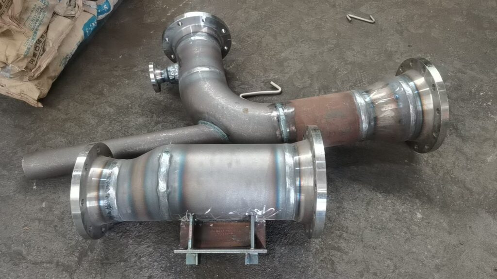
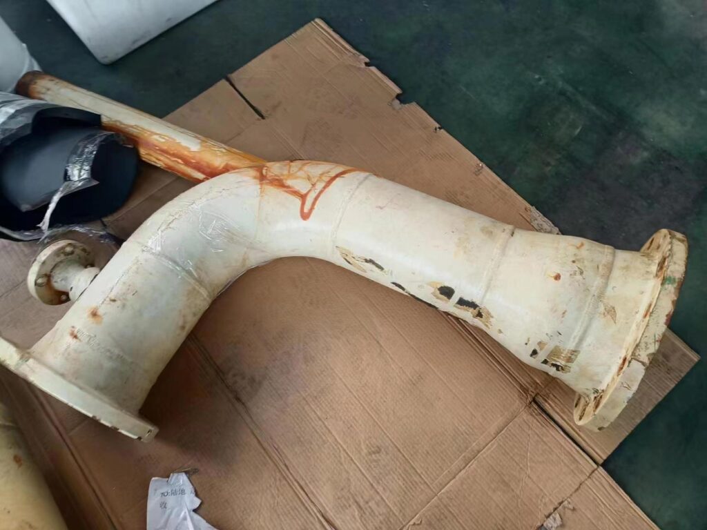
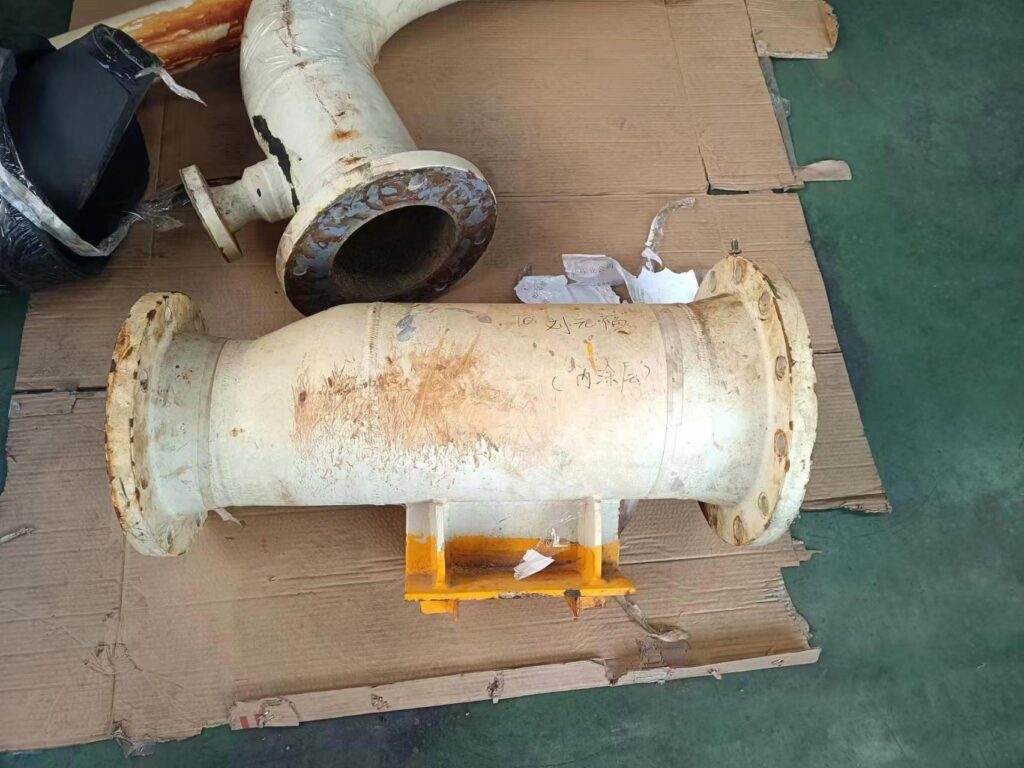
The customer’s factory repaired two pipe groups and entrusted our company to “copy” them. The pipe diameter is DN250-DN200, the wall thickness is STD, the material is ASTM A234 WPB, and the flanges at both ends are FF surface CLASS150 pressure level neck welding flanges, made of ASTM A105.

After production, our factory conducts X-ray inspection, size inspection, sprays epoxy anti-corrosion coating and then ships. The customer has installed it and is using it normally.

Additional Testing Requirement for duplex stainless steel material

Spread the love

Additional Requirement for DSS Material from LUFENG.

Charpy V-Notch (ASTM A370)
Not applicable when the maximum obtainable Charpy specimen width less than 2.5mm Absorbed energy shall be 61J average and 48J Single value minimum Test temperature shall be minus 46 deg C. Impact test specimen taken from mid-thickness position.

Ferrite Count (ASTM ES62)
Ferrite content shall be determined by manual point count on a cross section near OD, ID surface & midwall location. Sample shall be electrolytically etched in NaOH or KOH, and in such a manner as to provide optimum contrast for austenite and ferrite phase discrimination. Minimum 30 field and 16 points per field shall be used. Ferrite content shall be between 40% to 60%.

Metallographic Examination
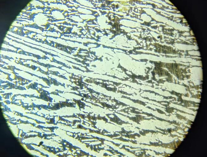
Sample shall be etched using ASTM E407, K3Fe (CN)6 with KOH or NaOH. Sample cross section shall be examined at OD, ID and midwall locations. Examination shall be conducted at a minimum of 400X to 500X magnification. Material shall be free of intermetallic phases and precipitates A microphotograph at a minimum of 400X to 500X shall be supplied.

Corrosion Test
Shall be carried out as per ASTM G4S at 25 deg C for 24 hours with an acceptance criteria of no visual pitting at 20X and weight loss of less than 4 g/m2.

NACE Hardness
Hardness test according to NACE MR-0175 the maximum shall be HRC 28, HB 271, or HV10 310.

Other Requirements
LUFENG representative examination required for heat number traceability, visual examination, dimensional examination and mill test certificate review. All testing required to be per heat number.

NOTE:
Duplex Stainless Steel (DSS)
All DSS Material shall be in accordance with a minimum PREN of 34 according to the formula:
PREN = %Cr + 3.3×(%Mo + 0.5×%W ) + 16×%N

ASTM A240 S31803

Spread the love

ASTM A240/A240M Standard Specification for Chromium and Chromium-Nickel Stainless Steel Plate, Sheet, and Strip for Pressure Vessels and for General Applications

Duplex (Austenitic-Ferritic) steel

UNS Designation : S31803

Chemical Composition Requirements, %
C: ≤0.030
Mn: ≤2.00
P: ≤0.030
S: ≤0.020
Si: ≤1.00
Cr: 21.0-23.0
Ni: 4.5-6.5
Mo: 2.5-3.5
N: 0.08-0.20

Mechanical Test Requirements
Tensile Strength: ≥620Mpa
Yield Strength: ≥450MPa
Elongation in 2 in. or 50 mm: ≥25%
Hardness:
Brinell: ≤293
Rockwell (C scale): ≤31
Cold bend: not required